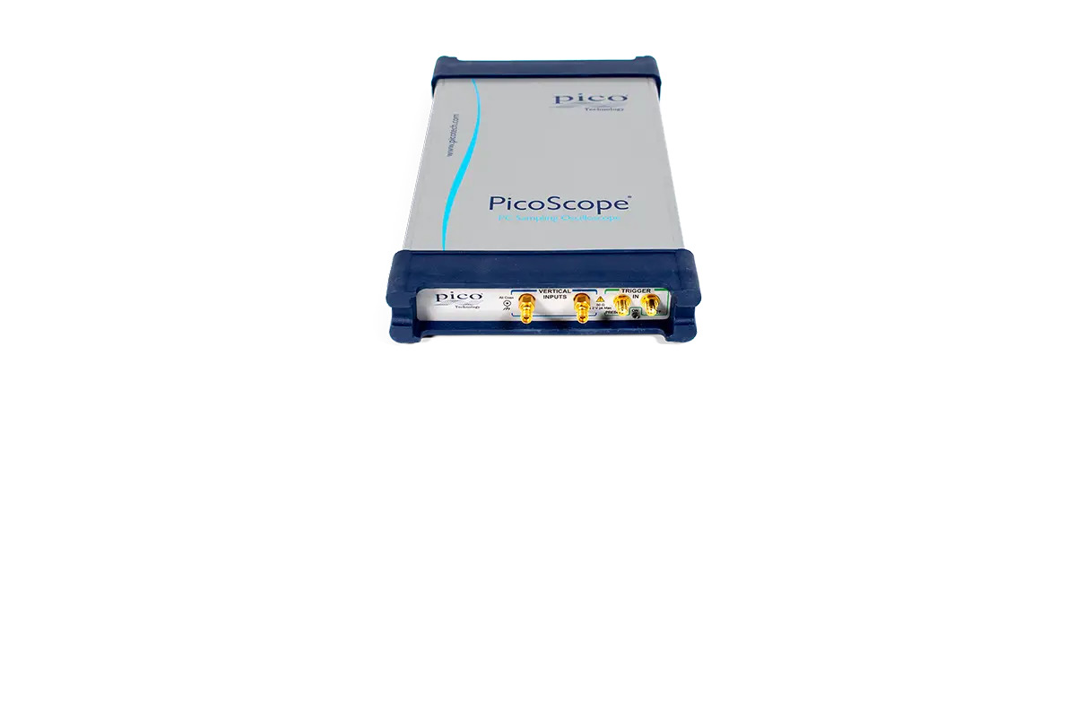
The PicoScope 9300 Series Sampling Oscilloscopes are developed for engineers who need to characterise repetitive high-frequency signals, picosecond transitions, serial data eyes, optical communication signals and transmission paths.
Unlike a conventional real-time oscilloscope, the PicoScope 9300 Series uses sequential equivalent-time sampling. It captures samples from repeated occurrences of a stable waveform and combines them to create a high-resolution representation of the signal.
The series provides:
- 20 GHz or 30 GHz electrical bandwidth
- Two or four analogue input channels
- 16-bit vertical resolution
- Up to 15 TS/s sequential sampling
- Timing resolution down to 64 fs
- Up to 1 MS/s digitising rate
- Record lengths up to 32,768 points
- 50 Ω high-frequency inputs
- Eye-diagram and mask testing
- Pulse and jitter measurements
- FFT and histogram analysis
- Optional clock recovery
- Optional optical input
- Optional integrated TDR/TDT sources
- USB and LAN connectivity
- PicoSample software
The series is intended primarily for repetitive signals. It should not be described as a general-purpose high-bandwidth real-time oscilloscope for capturing isolated 20 GHz or 30 GHz events.
Current PicoScope 9300 Model Range
| Model |
Channels |
Electrical Bandwidth |
Special Capability |
| PicoScope 9301-20 |
2 |
20 GHz |
Standard sampling oscilloscope |
| PicoScope 9301-30 |
2 |
30 GHz |
Higher-bandwidth sampling oscilloscope |
| PicoScope 9302-20 |
2 |
20 GHz |
Integrated 11.3 Gb/s clock recovery |
| PicoScope 9311-20 |
2 |
20 GHz |
Integrated differential TDR/TDT sources |
| PicoScope 9321-20 |
2 electrical |
20 GHz |
9.5 GHz optical input and clock recovery |
| PicoScope 9341-20 |
4 |
20 GHz |
Four-channel sampling oscilloscope |
| PicoScope 9341-30 |
4 |
30 GHz |
Four-channel, 30 GHz sampling oscilloscope |
The current official Pico product page lists these seven configurations. The model number should always be stated in the quotation because bandwidth, channel count and specialised hardware vary substantially.
20 GHz and 30 GHz Analogue Bandwidth
Current PicoScope 9300 models provide:
- 20 GHz full bandwidth on 9300-20 models
- 30 GHz full bandwidth on 9300-30 models
- 10 GHz narrow-band mode on 20 GHz models
- 20 GHz mid-band mode on 30 GHz models
- 12 GHz narrow-band mode on 30 GHz models
Calculated 10% to 90% rise time is:
- 17.5 ps at 20 GHz
- 11.7 ps at 30 GHz
- 35 ps in the 10 GHz narrow-band mode
- 29.2 ps in the 12 GHz narrow-band mode
These bandwidth levels support:
- High-speed serial data
- Microwave pulse analysis
- Clock and timing measurements
- Telecom transmitters and receivers
- Optical communication testing
- Semiconductor switching characterisation
- Radar pulse measurements
- Signal-integrity troubleshooting
- High-speed interconnect analysis
- Picosecond transition measurements
The complete measurement system also depends on the probe, cable, connector, adaptor and device-under-test connection.
Two-Channel and Four-Channel Models
Most PicoScope 9300 models provide two electrical input channels. The PicoScope 9341-20 and 9341-30 provide four channels.
Two-channel models support:
- Differential pair comparison
- Clock and data analysis
- Input and output comparison
- Pulse delay measurements
- Transmitter and receiver evaluation
- Phase and gain measurements
Four-channel models support:
- Multiple serial lanes
- Clock and several data signals
- Multi-path RF measurements
- Transmitter and receiver correlation
- Simultaneous timing analysis
- Multi-channel eye testing
- Four-signal pulse comparison
Acquisition timing can be configured for simultaneous or alternate operation, depending on the measurement requirement.
16-Bit Vertical Resolution
Every current PicoScope 9300 model uses a 16-bit acquisition system.
Key characteristics include:
- 65,536 vertical quantisation levels
- Approximately 40 µV per least significant bit
- Sensitivity from 1 mV/div to 500 mV/div
- 50 Ω nominal input impedance
- Digital feedback for improved measurement stability
- More than 60 dB dynamic range under applicable conditions
The high vertical resolution supports:
- Small amplitude variation analysis
- Eye-height measurement
- Pulse overshoot and undershoot
- Noise characterisation
- Amplitude histograms
- Optical power measurements
- Transmission loss measurement
- Semiconductor waveform analysis
The vertical accuracy is specified as ±2% of full scale plus ±2 mV under the stated operating and calibration conditions.
15 TS/s Sequential Equivalent-Time Sampling
The PicoScope 9300 Series offers sequential equivalent-time sampling up to 15 TS/s, corresponding to a sampling interval of approximately 64 fs.
Sequential sampling is used for repetitive waveforms. The oscilloscope captures one or more samples after each trigger and progressively moves the sampling point across the signal.
This provides detailed representation of:
- Picosecond waveform transitions
- Repetitive clock edges
- Serial data eyes
- Microwave pulses
- Optical receiver outputs
- Jitter distributions
- Pulse ringing and aberrations
- Inter-symbol interference
The effective 15 TS/s figure should not be described as a real-time sampling rate. It is achieved by combining repeated acquisitions of a stable signal.
1 MS/s Digitising Rate
The 16-bit ADC provides a digitising rate up to:
- 1 MS/s with digital feedback
- 40 kS/s without digital feedback in multi-valued acquisition
The digitising rate describes the rate at which waveform points are acquired during the sequential sampling process. It is separate from the effective 15 TS/s time resolution.
The product page should clearly distinguish:
- 15 TS/s equivalent-time sampling
- 1 MS/s ADC digitising
- 64 fs timing resolution
32 kS Record Length
The PicoScope 9300 Series supports data record lengths from:
- 32 points
- Up to 32,768 points on one channel
The record length is suitable for:
- Eye-diagram acquisition
- Pulse characterisation
- Pattern-locked analysis
- Waveform averaging
- Histogram generation
- Timing and phase measurements
- Mask testing
The series is optimised for high timing resolution and repetitive waveform analysis rather than long-duration gigasample recording.
Advanced Trigger System
Trigger sources include:
- External direct trigger
- External prescaled trigger
- Internal direct trigger
- Internal clock trigger
- Clock recovery trigger on supported models
The external direct trigger supports frequencies up to approximately 2.5 GHz.
Prescaled triggering supports:
- Up to 14 GHz on 20 GHz configurations
- Up to 18 GHz on 30 GHz configurations
Pattern synchronisation supports clock frequencies from 10 MHz to 14 GHz or 18 GHz, depending on model, with pattern lengths up to 223−12^{23}-1223−1.
Low trigger jitter supports accurate:
- Eye-diagram generation
- Clock measurements
- Pulse-width analysis
- Timing-delay measurement
- Phase analysis
- Serial data characterisation
11.3 Gb/s Clock Recovery
The PicoScope 9302-20 and PicoScope 9321-20 include an integrated clock recovery system.
Clock recovery supports:
- Data rates from 6.5 Mb/s to 11.3 Gb/s
- Recovered-clock triggering
- Lower trigger jitter on serial data
- Data streams without a separate clock
- Pattern-lock measurements
- Eye-diagram testing
- Telecom and optical receiver analysis
The recovered clock trigger has typical jitter of approximately 1 ps plus a proportion of the signal unit interval.
Clock recovery is model-specific. It should not be presented as standard across every PicoScope 9300 instrument.
Integrated TDR and TDT Testing
The PicoScope 9311-20 includes two integrated step sources configured as a differential pair.
TDR/TDT source specifications include:
- Two source outputs
- Positive and negative polarity
- 60 ps guaranteed rise time
- Adjustable amplitude from 2.5 V to 7 V into 50 Ω
- Independent or linked output control
- Deskew from approximately -1 ns to +1 ns
- Deskew adjustment in 1 ps increments
- SMA output connectors
- TDR, TDT and pulse operating modes
TDR and TDT testing can be used to characterise:
- Cables
- Connectors
- PCB traces
- Backplanes
- Transmission lines
- Differential interconnects
- Impedance discontinuities
- Propagation delay
- Reflection coefficient
- Fault position
Any PicoScope 9300 model can also be used with a separate PicoSource PG900 pulse generator for external TDR/TDT testing.
9.5 GHz Optical Input
The PicoScope 9321-20 includes an integrated optical-to-electrical converter.
Optical characteristics include:
- 9.5 GHz typical bandwidth
- 750 nm to 1650 nm wavelength range
- Calibration at 850 nm, 1310 nm and 1550 nm
- Single-mode and multimode fibre support
- FC/PC optical connector
- Approximately 51 ps calculated transition time
- Integrated 11.3 Gb/s clock recovery
It is suitable for:
- Optical transmitter testing
- Optical receiver evaluation
- Fibre Channel
- Optical Ethernet
- SONET and SDH
- Laser and photodiode testing
- Optical eye diagrams
- Extinction ratio measurement
- Optical signal-to-noise analysis
The optical input is exclusive to the PicoScope 9321-20 configuration.
Eye-Diagram Analysis
PicoSample software automatically analyses NRZ and RZ eye patterns.
Eye measurements include:
- Bit rate
- Bit time
- Eye width
- Eye height
- Eye amplitude
- Crossing percentage
- Rise and fall time
- Peak-to-peak jitter
- RMS jitter
- Extinction ratio
- Signal-to-noise ratio
- Overshoot
- One and zero noise
- Duty-cycle distortion
Up to ten measurements can be displayed simultaneously, with statistics applied to repeated acquisitions.
Pattern synchronisation and eye-line modes allow engineers to examine data-dependent behaviour across a repeating bit pattern.
Mask Testing
The PicoScope 9300 Series includes standard and user-defined mask testing.
Mask analysis supports:
- Pass and fail counting
- User-defined margins
- Stop-on-fail operation
- Mask-hit capture
- Editable masks
- Statistical eye display
- Standard communication masks
- User-created compliance limits
Supported mask categories include:
- SONET and SDH
- Ethernet
- USB 2.0
- USB 3.0 and USB 3.1
- Fibre Channel
- ANSI telecom standards
- PAM4 eye measurements
- Other high-speed communication formats
Pico Technology includes the analysis software and feature updates without separate software licence charges.
Automatic Measurements and Statistics
The PicoScope 9300 Series supports more than 100 waveform and eye parameters.
Measurement categories include:
- Voltage
- Time
- Frequency
- Pulse width
- Rise and fall time
- Duty cycle
- Jitter
- Overshoot
- RMS
- Area
- Gain
- Phase
- Delay
- Eye parameters
Up to ten automatic measurements can be displayed simultaneously.
Measurements can be performed:
- Across the complete waveform
- Between selected markers
- On live traces
- On stored waveform memories
- On mathematical waveforms
- With statistical analysis
FFT, Mathematics and Histograms
The software supports up to four mathematical waveforms.
Functions include:
- Addition
- Subtraction
- Multiplication
- Division
- Differentiation
- Integration
- Logarithmic functions
- Trigonometric functions
- Logic operations
- Interpolation
- Custom formulas
- Complex FFT
- Inverse FFT
- Magnitude, phase, real and imaginary FFT components
Histogram analysis supports:
- Horizontal timing histograms
- Vertical amplitude histograms
- Noise distribution
- Jitter distribution
- Measurement variation
- Statistical waveform analysis
Compact USB and LAN Instrument
The PicoScope 9300 Series uses an external computer for display and control.
Physical and connectivity characteristics include:
- USB 2.0 connection, compatible with USB 3.0 ports
- 10/100 Mbit/s LAN connection
- External 12 V DC power adaptor
- Dimensions of approximately 170 × 285 × 40 mm
- Maximum weight of approximately 1.3 kg
- Five-year manufacturer warranty
- Annual calibration interval
Its compact design allows the instrument to be positioned close to the device under test, reducing the length and loss of high-frequency coaxial connections.
Applications
The PicoScope 9300 Series is suitable for:
- High-speed digital design
- Signal-integrity testing
- Telecom system validation
- Optical communication analysis
- Microwave pulse measurement
- Radar development
- Clock and jitter analysis
- Serial data eye testing
- Semiconductor characterisation
- TDR and TDT measurements
- Cable and connector testing
- PCB and backplane analysis
- Fibre transceiver testing
- Laser and optical receiver evaluation
- USB, Ethernet, HDMI, PCIe and SATA testing
- Production validation
- Research laboratory measurements